


Description
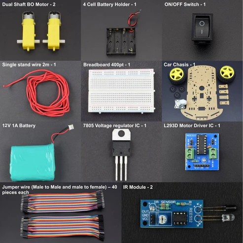
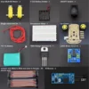
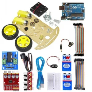
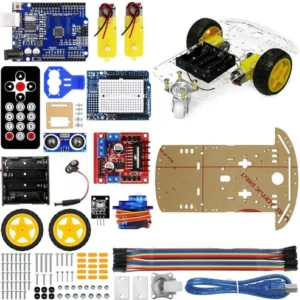
KIT INCLUDES:
- IR Module – 2
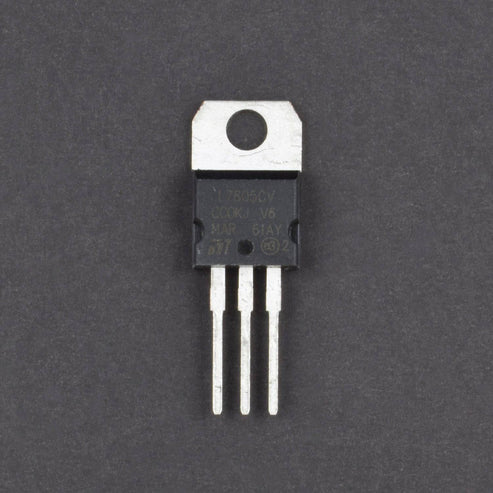
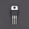
- 7805 Voltage regulator IC – 1
- L293D Motor Driver IC – 1
- ON/OFF SPST Switch – 1
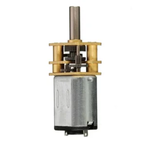
- Dual Shaft BO Motor – 2
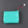
- 12V 1A LI-PO Battery – 1
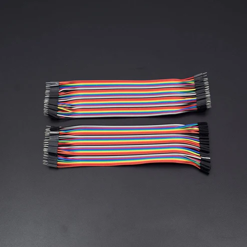
- Jumper wire (Male to Male)-40 PCS
- Jumper Wires (male to female) – 40 pieces
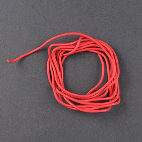
- Single stand wire 2m – 1
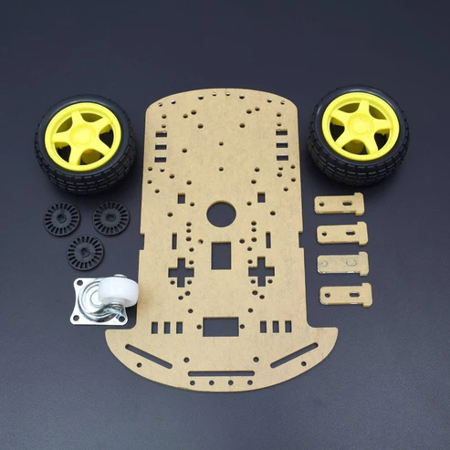
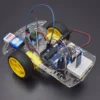
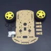
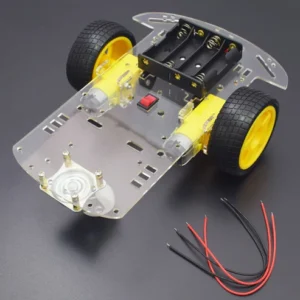
- 2 Wheel Car Chassis KIT – 1
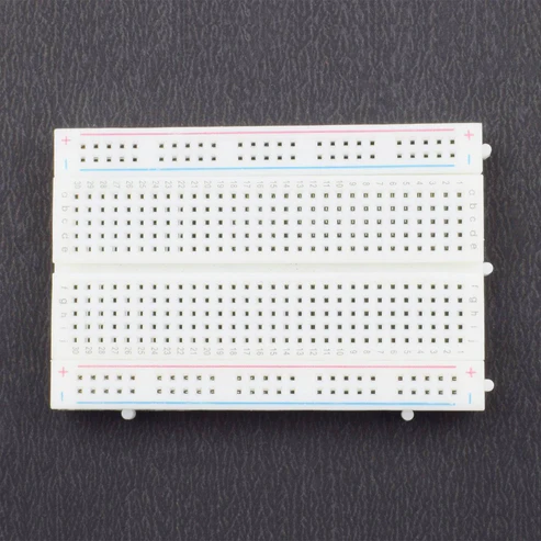
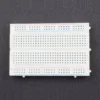
- Breadboard 400 points – 1
HARDWARE REQUIRED
- IR Module – 2
- 7805 Voltage regulator IC – 1
- L293D Motor Driver IC – 1
- ON/OFF SPST Switch – 1
- Dual Shaft BO Motor – 2
- 12V 1A LI-PO Battery – 1
- Jumper wire (Male to Male)-40 PCS
- Jumper Wires (male to female) – 40 pieces
- Single stand wire 2m – 1
- 2 Wheel Car Chassis KIT – 1
- Breadboard 400 points – 1
PIN DESCRIPTION
7805 VOLTAGE REGULATOR

IR SENSOR MODULE

When it detects an obstacle within range it will send an output low.
| VCC | 5V |
| GND | GND |
| OUT | Serial output to signal |
L293D MOTOR DRIVER IC

| Pin No | Function | Name |
| 1 | Enable pin for Motor 1; active high | Enable 1,2 |
| 2 | Input 1 for Motor 1 | Input 1 |
| 3 | Output 1 for Motor 1 | Output 1 |
| 4 | Ground (0V) | Ground |
| 5 | Ground (0V) | Ground |
| 6 | Output 2 for Motor 1 | Output 2 |
| 7 | Input 2 for Motor 1 | Input 2 |
| 8 | Supply voltage for Motors; 9-12V (up to 36V) | Vcc 2 |
| 9 | Enable pin for Motor 2; active high | Enable 3,4 |
| 10 | Input 1 for Motor 1 | Input 3 |
| 11 | Output 1 for Motor 1 | Output 3 |
| 12 | Ground (0V) | Ground |
| 13 | Ground (0V) | Ground |
| 14 | Output 2 for Motor 1 | Output 4 |
| 15 | Input2 for Motor 1 | Input 4 |
| 16 | Supply voltage; 5V (up to 36V) | Vcc 1 |
CIRCUIT DESCRIPTION

- Make Positive rail and negative rail on a breadboard by connecting Positive and negative supply.
- Connect L293D Motor Driver IC and 7805 Voltage regulator IC to the Breadboard.
- Connect L293D IC Pin No. 1, 7, 8, 9, 10 & 16 connected to the Pin No. 3 OUT of 7805 IC.
- Connect L293D IC Pin No. 4, 5, 12 & 13 to the GND
- 7805 IC Pin No. 2 is GND and Pin No. 1 connected to the ON/OFF Switch pin 1st, ON/OFF switch pin 2nd connected to the positive supply of LI-PO Battery
- BO Motor 1st connected to the L293D IC Pin No. 11 & 14 and BO Motor 2nd connection to the L293D IC Pin No. 3 & 6.
- IR Module 1st pin vcc connected to the L293D IC Pin no. 9 and GND pin connected to the GND and o/p pin connected to the L293D IC pin no. 15.
- IR Module 2nd pin vcc connected to the L293D IC Pin no. 8 and GND pin connected to the GND and o/p pin connected to the L293D IC pin no. 2.
WORKING
line follower robot follow the line draw on white sheet or an specified path provided by the user. working IR sensor that reflect the light rays to white chart black line absorb the rays and ir sensor provide signal to the LM358 comparator IC that works on the principle.
Block Diagram of the Project
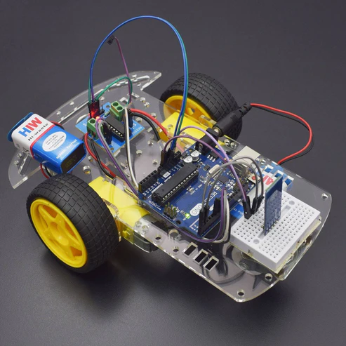
The line follower robot built in this project is divided in to 4 blocks. The following image shows the block diagram for line follower robot.
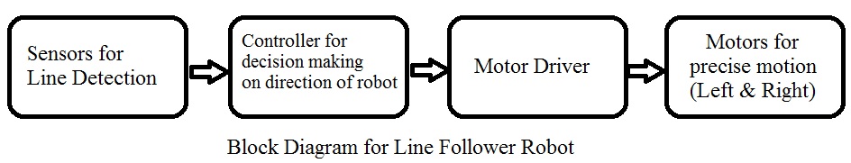
In this project, we have designed an Arduino based Line Follower Robot. The working of the project is pretty simple: detect the black line on the surface and move along that line. The detailed working is explained here.
As mentioned in the block diagram, we need sensors to detect the line. For line detection logic, we used two IR Sensors, which consists of IR LED and Photodiode. They are placed in a reflective way i.e. side – by – side so that whenever they come in to proximity of a reflective surface, the light emitted by IR LED will be detected by Photo diode.
The following image shows the working of a typical IR Sensor (IR LED – Photodiode pair) in front of a light coloured surface and a black surface. As the reflectance of the light coloured surface is high, the infrared light emitted by IR LED will be maximum reflected and will be detected by the Photodiode.
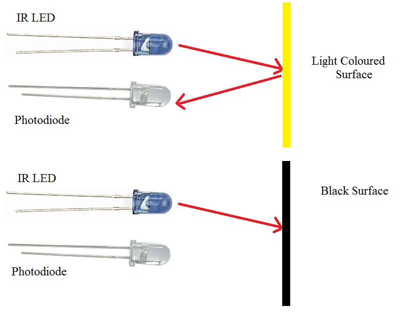
In case of black surface, which has a low reflectance, the light gets completely absorbed by the black surface and doesn’t reach the photodiode.
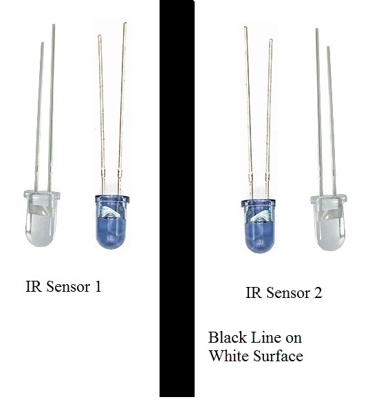
Using the same principle, we will setup the IR Sensors on the Line Follower Robot such that the two IR Sensors are on the either side of the black line on the floor. The setup is shown below.
When the robot moves forward, both the sensors wait for the line to be detected. For example, if the IR Sensor 1 in the above image detects the black line, it means that there is a right curve (or turn) ahead.
Arduino UNO detects this change and sends signal to motor driver accordingly. In order to turn right, the motor on the right side of the robot is slowed down using PWM, while the motor on the left side is run at normal speed.
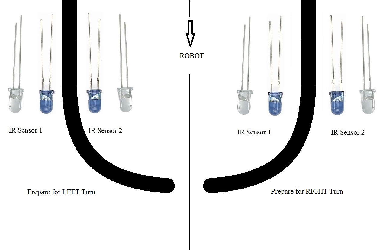
Similarly, when the IR Sensor 2 detects the black line first, it means that there is a left curve ahead and the robot has to turn left. For the robot to turn left, the motor on the left side of the robot is slowed down (or can be stopped completely or can be rotated in opposite direction) and the motor on the right side is run at normal speed.
Arduino UNO continuously monitors the data from both the sensors and turns the robot as per the line detected by them.


 Official Raspberry Pi Zero Case Compatible with Raspberry Pi Zero, Zero W, Zero 2W
 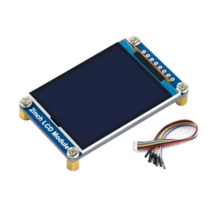 Waveshare 2" IPS LCD Display Module 240x320 SPI Interface LCD Display Module
 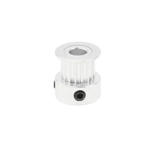 GT2 Timing Pulley Aluminum GT2 Timing Pulley 16 Tooth 5mm Bore For 6mm Belt
  Raspberry Pi 5MP Camera Module Raspberry Pi Camera v1.3 with Cable High-Quality Camera for Raspberry Pi 3/4 Model B/B+
  300 Pieces 15 Value 1KV 2KV 3KV High Voltage Ceramic Capacitor Assortment Set Kit with Clear Plastic Box
  Raspberry Pi Zero V1.3 Single-Core CPU Support Micro USB Power, Camera And Micro SD Card
  Raspberry Pi 4 Model-B 2GB SDRAM Raspberry PI 4B SBC IOT Board - Broadcom 1.5GHZ A72 Processor
  DC Motor Fan Blade 3-Wing Fan For Toy Motor Round Sape - Red
  No Touch Stainless Steel Door Exit Switch/Touch Free Exit Push Release Button Switch for Electric Access Control
  iMAX B6 Charger iMAX B6 80W 6A Charger/Discharger 1-6 Cells
  Bambu Lab TPU 95A HF 1.75mm 3D Filament Grey
  ReadytoSky 30A ESC 2-6S Brushless Speed Controller For RC Quad Multicopter High-Current ESC For Drone Racing
  Bambu Lab TPU 95A HF 1.75mm 3D Filament Black
  N20 3V Vibration Motor Compact DC Vibration Motor With Counter Weight Vibration Motor For Electronics High-Performance Vibration Motor Powerful Small Vibration Motor For Wearable Devices
Reviews
There are no reviews yet.