


Description
Description:
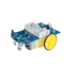
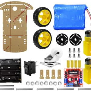
Smart robot cars are the most widely used in school for helping students to learn about the soldering project knowledge of automatic control, voltage comparator, motor drive circuit, mechanical structure, electronic basis skills, the principle of sensor, automatic control, soldering skill and so on.
As the light reflectivity is different when the light is emitting on the white and black items. It uses the photoresistor to tell if the smart car is on the right way or not. Smart tracking car can discriminate the direction automatically so that they can run freely along the black tracking line.
Features:
Photosensitive resistance device-
This is light-sensitive resistance, it can detect the external light intensity, the stronger the outside light photosensitive resistance resistance is, the outside light resistance is greater when the red LED light is projected on a white and black runway because the reflection rate is different, the resistance value of the light-sensitive resistance will occur obvious difference for subsequent circuit control.
LM393 comparator integrated circuit-
LM393 is a dual voltage comparator integrated circuit, which consists of two independent precision voltage comparators. its role compare the two input voltage, based on the level of the two input voltage changes the level of output voltage. The output has two states: close to open or close to the low level, LM393 uses open collector output, so it is necessary to add the pull resistance to the output high level.
DC motor with gear reduction-
DC motor drive the car needs to slow down, otherwise to speed up the car, then run too fast not control, and the deceleration torque is too small and cannot run up. We specialize in the custom of this type of motor is integrated with the reduction gear and greatly reduces the manufacturing difficulty is very suitable for our use.
How to Assemble:
First Step: Circuit part of the basic welding-
The welding circuit part is relatively simple, the welding sequence according to the element height from low to high, the first 8 resistance welding, welding must use a multimeter to confirm whether the proper welding resistance, polar components such as transistors, green lights, definitely clear electrolytic capacitor polarity as reference element we are photo welding, welding capacitor short is the negative side of the insertion pin PCB screen printing shadow, green welding LED note long pin is positive, and the welding is not too long or easy bad welding, D4 D5 R13 R14 can temporarily do not weld, the integrated circuit chip can be inserted, preliminary after completion of welding check carefully prevent, be negligent.
Second Step: Mechanical assembly-
The universal wheel screw is inserted into the PCB hole, and screwed into the universal wheel nut and a universal wheel. the battery box is stuck on the PCB by the double adhesive tape, the lead wire passes the PCB reserved Kong Han received PCB, the red line is connected with the 3 V positive power supply and the yellow line is connected to the ground.
Mechanical part and assembly can be mounted first wheels, wheel consists of three pieces of black acrylic round tablets, assembly prior to exposing the protective film, the inside of the wheel’s centre hole grows circular hole, middle of the round plate diameter is relatively small, lateral wheel piece centre hole Shiyuan, with two screw nuts fixed set good three round tablets, and black self-tapping screws fixed on the rotating shaft of the engine. Finally the silicone rubber tire sleeve on the wheel. Lead connection lead wire of the motor and the wheel assembly is the use of the glue on the PCB making position, attention wheels and the PCB edge retaining sufficient clearance, the motor leads are soldered to the PCB. Note that adequately longer lead, to avoid the motor rotation direction error is convenient for changing the lead wire of the order.
Third Step: The installation of optoelectronic circuits-
Photosensitive resistance and light-emitting diode (attention polarity) is the reverse installed on the PCB, and the ground distance of about 5mm, and the distance between the light-sensitive resistance and light-emitting diode is also about 5mm. Finally can pass electrical test.
Fourth Step: Vehicle debugging-
In the battery box in 2 AA batteries, switches to dial in the “on”, the car driving right reverse is travelling along the direction of the universal wheel, if hold the left side of the photosensitive resistance, the car to the right of the wheel rotation, Keep to the right of photosensitive resistance, the left side of the car wheel must turn, if car travel back can exchange connection of two motors at the same time. as one of the normal backs on the other side as long as the exchange of the rear of the motor can be wiring.
Package Included:
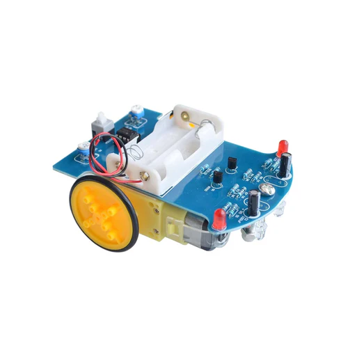
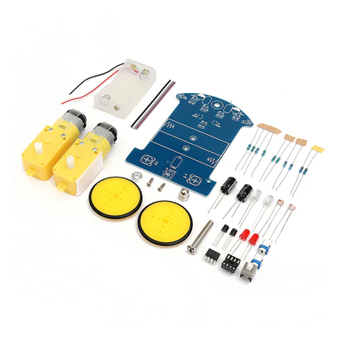
1 x DIY D2-1 Intelligent Line Follower Car Kit DIY Smart Tracking Robot Car Electronic Kit With Reduction Motor Set


 1*40 Single Row Female Pin Header Connector Strip(2.54mm Pitch)
 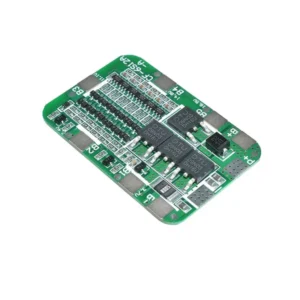 24V 6S 15A BMS Board BMS 6S 15A 24V Battery Protection Board For 18650 Li-ion Battery Cell Protection Board For 18650 Lithium Battery
 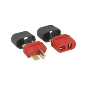 T Plug Deans Connector XT Plug T Plug Deans Connector For Esc Battery Male Female With Seath Housing
 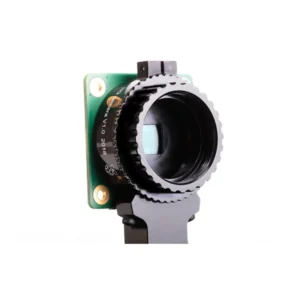 Raspberry Pi High Quality Camera RPi Cam High Quality High-Resolution Premium Camera Module C/CS Mount Or M12 Mount For Your Pi Projects
 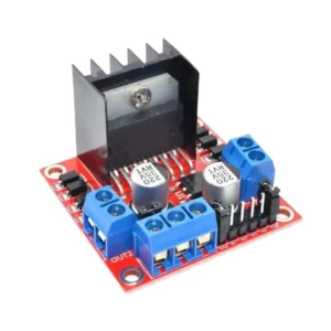 L298N Based Dual Motor Driver Speed And Direction Control Raspberry Pi-Controlled Dual Motor Driver Motor Driver Circuit Build Your Own Robot
  4 x 18650 Battery Holder 18650 Battery Case Plastic Storage Box Holder For 4 Cell 18650 Battery Storage Box Without Cover - Black
 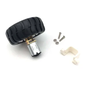 N20 Motor with Wheel N20 Geared Motor Rubber Wheel Kit 12V
  Raspberry Pi Compute Module 4 - CM4001008 - 1GB RAM 8GB eMMC No Wireless
 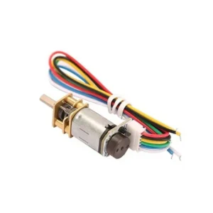 GA12-N20-12V 1000 RPM ALL METAL GEAR MICRO DC MOTOR WITH PRECIOUS METAL BRUSH
  Bambu Lab PETG-CF 3D Printer Filament 1.75mm Brick Red
  4-Pin 10mm LED Connector 4-Pin 10mm Waterproof LED Connector 10mm Male/Female LED Connector For RGB / RGBW / RGBWW Colour 5050 LED Strips, Pack Of 2
Reviews
There are no reviews yet.